Four-Bar
The Four-Bar design is a very widely used strategy that allows a large amount of adjustment of spring leverage ratios. The four-bar linkage design was the next step in the evolution of bicycle suspension. It was a lighter, more versatile design that, if built well, is a rock-solid choice for manufacturers. The main idea is the linkages and components represent a four-sided polygon: the chain stay, seat stay, rocker, and seat tube. The design is similar in principal to independent front suspension common in vehicles. There are different versions of this design, and each vary ever so slightly. But, each has their own patient filed with the US Patient Office.
The only difference is where the pivot is mounted near the axle. If the link is above or behind the axle, with the axle attached to the chain stay, it is considered a bona fide single pivot with cool linkages (like the image below). If the pivot combines 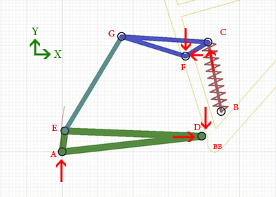 the seat and chain stays at the axle, it is called the Split Pivot. If the pivot is directly in front of the rear axle, with the axle attached to the seat stay, it is called a Horst link. The way this design works is similar to most independent front suspension designs in a car. The wheel is mounted at Point A, and the chain stay pivots around point D. The rocker, (triangle made up by points C, F and G) is pivoted around point F. This is the device that transfers vertical movement by the rear axle to the shock.
The first type is displayed in the image to the right. The rear pivot is above the axle (Point E), with the axle attached to the chain stay (Point A), and has the same exact wheel path as a single pivot design. The only difference is that it may be more reactive to bumps because it is lighter. Brake-induced lockout will be an issue if the rear caliper is attached to the seat stay instead of the chain stay.
The second design, called the Split Pivot, is where the pivot is coaxial with the wheel axle. It is in where (in the image above) the points A and E become the same. It is claimed by designers to eliminate brake-induced lockout because the braking forces are isolated from the suspension. This is a lie and is simply a marketing tool. Anyone with even a mild physics background is aware of Newton's third law about equal and opposite reactions. One cannot simply make a clever linkage design and have a braking force magically disappear. The energy must go somewhere, which happens to be in increasing the apparent spring rate at the wheel (thus being 'locked out').
The third  main design of the four bar is the Horst link, which is displayed below. This is one of the oldest designs and is an attempt to veer from the traditional pivot-concentric wheel path. One could consider this having a 'virtual pivot point', which would be located just behind the point F, but it is more appropriate to categorize it as a four bar because of the linkage design. The advantage to this path is that the slope of the wheel path when there is no compression, which has a smaller slope (is less vertical) than a single pivot design, and allows for a more active suspension over small bumps.
You will see the difference between this and a real virtual pivot setup on the virtual pivot page. Again, as the Split Pivot design does, the Horst link has an issue with brake-induced lockout because the rear brake caliper is attached to the seat stay.