In the above links, seven basic suspension designs are listed. These are either the most broadly used on the market today or have specific problem-solving relevance. Some provide a better ride than others in different situations. The main problems associated to providing rear suspension on a bicycle are leverage ratios, pedal bob, brake jack and wheel path, all of which are discussed below. Some of the bike component names can be confusing, so there will be a few terms covered. There has been an attempt to keep the layout and point/pivot variables between the diagrams similar. All of the images have red arrows on them, which signify the forces on the system (which is the moving links).
Also, as a side note, there are many claims out there by manufacturers that can be debunked by a semi-complex mechanical analysis (which will not be shown). Unfortunately, a lot of these claims have been taken for truth by the cycling world (and have even made it into Wikipedia). If you are interested, there is a link in the About page to a one hundred page document with mechanical analyses that expose false claims (called Path Analysis) of all the major suspension designs here.
Terms
Bottom bracket - The device that contains the pedal cranks axle.
Seat stay - Bar or linkage that is in the general direction between the rear axle and the seat.
Chain stay - Bar or linkage that is between the rear axle and the bottom bracket.
Seat tube - Near-vertical tube in which seat post slides and locks.
Down tube - Long diagonal tube or bar that connects the bottom bracket and the front of the bike.
Spring shock - Suspension shock that uses a metal spring to provide resistance.
Air shock - Suspension shock that uses compressed air to provide resistance.
Coaxial - Having a common axis; in line with one another.
Spring Constants and Leverage Ratios
One of the design aspects of suspension is being able to manipulate the measurable resistance at the rear wheel (spring constant of the system). This is done through changing the angle at which force is applied to the shock by some linkage. The ratio between the rear axle (Point A) and the shock-mounting eye (Point C) is called the leverage ratio. The benefits of adjusting this are quite vast. We will use the figure below to expand on this.
Refer to the image below. In all designs, the leverage ratio on the rear shock changes as the suspension changes its position. Because of this, the apparent spring constant at Point A will not be linear. As the swing arm rotates clockwise and compresses the shock, the force vector unto the shock will not always be in line (coaxial) with the shock's long axis. Because of this, the force being transmitted through the shock will become equal to [F/cos(90-q)], where q is the angle DCB and F is the force applied by point C, tangent to the rotation of C about D (or in the opposite direction of that arrow near the point C in the image below). 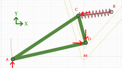 As the swing arm travels through its path, this angle will start out less than 90º, then reach 90º, and then become less than 90º again as the suspension reaches maximum travel. With this, the spring constant at the wheel will have a curve shape concave down, but still a positive slope throughout the travel.
Different leverage ratio curves can have many different benefits. This design in particular will have a digressive slope, allowing for a smoother ride regardless of where the swing arm is at, and is normally found on bikes with lots of suspension travel. Bikes with short travel are usually designed with an at-wheel spring constant plot that has a sharp rise (progressive) deep into the travel, helping to prevent hard bottom-outs of the suspension.
In addition, air shocks will have a progressive spring constant deeper into the travel than a coil shock, which is more linear.
Pedal Bob and Feedback
Pedal bob comes from the changing distance between the wheel axle (where the chain cogs are attached, Point A on the above image) and the pedal crank axle, or bottom bracket (marked BB on the above image). Since the pivot for the swing arm is not coaxial with the bottom bracket, whenever there is chain tension, there will be a torque on the swing arm in the counterclockwise direction. This will change the position of the suspension as the rider pedals up a hill, inducing "pedal bob". Preventing pedal bob will require a path that is concentric to a point just above the bottom bracket, to allow just enough torque on the swing arm to counter the rider's rhythmic bouncing while pedaling.
Another form of suspension induced pedal movement is bump feedback, which is also due to the lengthening distance between the axle and bottom bracket. It is possible when the suspension compresses the rider will feel either a force opposite to his pedaling or a sudden ease in pedaling.
Brake-Induced Lockout
Brake jack, or brake-induced lockout, is when the geometry of the rear suspension creates a situation that locks out the suspension when the rear brake is applied. In this case, when the brake applies a force to one of the suspension members, it forces the entire system to decompress, and lifts (and stiffens) the rear suspension. This is detrimental to off-road riders, as when they're going downhill, it's often across roots and rough terrain. A suspension design with brake jack symptoms will lock out as the rider tries to apply the brakes, resulting in the rear tire skipping over the top of bumps, offering no traction to slow down with.
Wheel Path
The wheel path is an extremely important aspect to keep a close eye on, as the reactivity to various forces (including pedal-bob and bump impacts) will be different for even the most minute changes in path. For reasons beyond what is possible to explain here, the most ideal path to take care of bump impacts, pedal-bob, and brake-induced lockout is an S shape. In shallow travel, the path should begin sloping away from the bike frame (as it does in the image above, but with opposite concavity), and then about halfway through the full travel, it changes concavity and the path comes back towards the bike frame. The only design to have accomplished this was the failed first version of the Virtual Pivot, which will be covered on its own page.