The Physics Of Trusses
Trust the truss
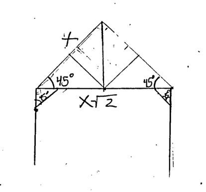 To the right, is an English Box
Truss. It is one of the more simplistic trusses that is used
in timber framing. There are variations where the timber
framer may curve all pieces with exception to the rafters
(the outside of the triangle) and the king post (the
vertical center piece). It is worth noting that this truss
is a right isosceles triangle. That means that each rafter
is the same length and this lends itself to the strength of
the triangle. Another common characteristic is that the
supporting members often connect in the middle of the
rafter. This is to ensure that the point load is directed
into the plate. The limitations of this truss is that you
must have a piece of timber that can span what ever length
is required to reach the breadth of the structure. Further,
the strength of the plate must be immense as it all
translates into the weakest point which is in the center of
the plate.
To the right, is an English Box
Truss. It is one of the more simplistic trusses that is used
in timber framing. There are variations where the timber
framer may curve all pieces with exception to the rafters
(the outside of the triangle) and the king post (the
vertical center piece). It is worth noting that this truss
is a right isosceles triangle. That means that each rafter
is the same length and this lends itself to the strength of
the triangle. Another common characteristic is that the
supporting members often connect in the middle of the
rafter. This is to ensure that the point load is directed
into the plate. The limitations of this truss is that you
must have a piece of timber that can span what ever length
is required to reach the breadth of the structure. Further,
the strength of the plate must be immense as it all
translates into the weakest point which is in the center of
the plate.
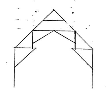 This is an example
of a hammer beam truss. You may not recognize it right away
but it is seen in much of our famed architecture such as
Westminster hall and Annenberg hall. The Annenberg hall may
not sound as familiar but it is also known as the Harvard
freshmen dining hall and was used as the model for the
Hogwarts dining hall.
This is an example
of a hammer beam truss. You may not recognize it right away
but it is seen in much of our famed architecture such as
Westminster hall and Annenberg hall. The Annenberg hall may
not sound as familiar but it is also known as the Harvard
freshmen dining hall and was used as the model for the
Hogwarts dining hall.
 Within this photo
there is striking beauty due to the lighting, the vaulted
ceiling, and the gorgeously woven wood and stone work. Where
the curve hammer beams are resting on the stone masonry
work.
Within this photo
there is striking beauty due to the lighting, the vaulted
ceiling, and the gorgeously woven wood and stone work. Where
the curve hammer beams are resting on the stone masonry
work.
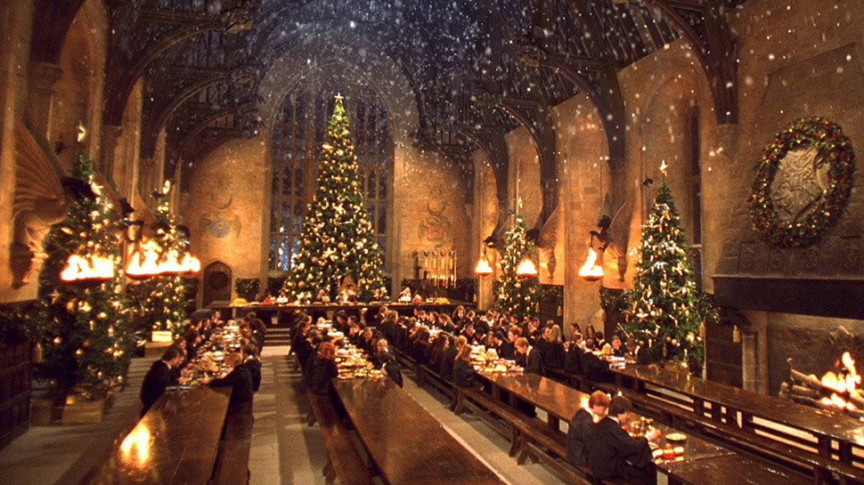
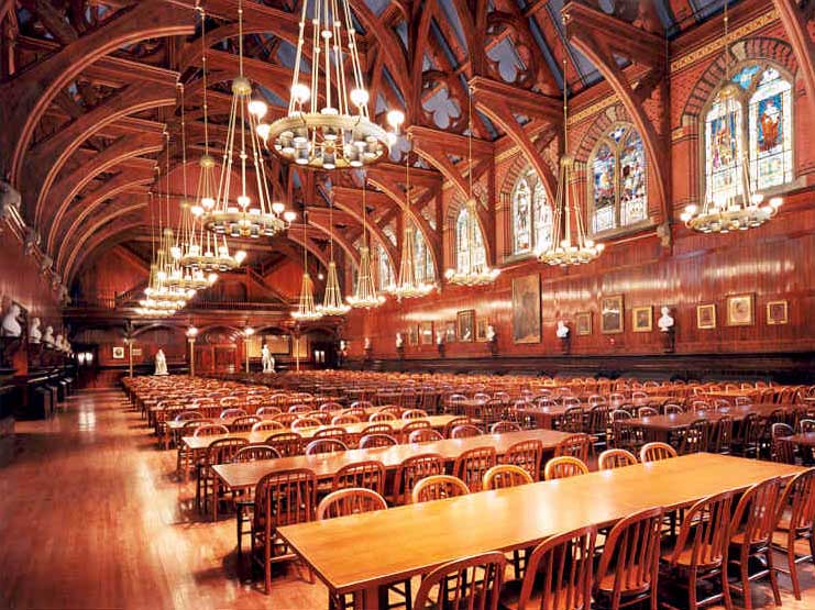 This is a real photo of Annenberg Hall. It is much brighter,
as there are windows, the masonry is actually wooden walls
yet the magical-ness is still there due to the vast span of
the room and also the vaulted ceiling.
This is a real photo of Annenberg Hall. It is much brighter,
as there are windows, the masonry is actually wooden walls
yet the magical-ness is still there due to the vast span of
the room and also the vaulted ceiling.
 This image
demonstrates a 3D model and how it would have a point
loading in the center. Upon inspection you will notice
that Bay 2, in-between bent 2 and 3 is the smallest. This
allows for there to be less of a moment or torque placed
upon bent 2 and 3.
This image
demonstrates a 3D model and how it would have a point
loading in the center. Upon inspection you will notice
that Bay 2, in-between bent 2 and 3 is the smallest. This
allows for there to be less of a moment or torque placed
upon bent 2 and 3.
- The Inspected Truss types
To the right, is an English Box
Truss. It is one of the more simplistic trusses that is used
in timber framing. There are variations where the timber
framer may curve all pieces with exception to the rafters
(the outside of the triangle) and the king post (the
vertical center piece). It is worth noting that this truss
is a right isosceles triangle. That means that each rafter
is the same length and this lends itself to the strength of
the triangle. Another common characteristic is that the
supporting members often connect in the middle of the
rafter. This is to ensure that the point load is directed
into the plate. The limitations of this truss is that you
must have a piece of timber that can span what ever length
is required to reach the breadth of the structure. Further,
the strength of the plate must be immense as it all
translates into the weakest point which is in the center of
the plate.This is an example
of a hammer beam truss. You may not recognize it right away
but it is seen in much of our famed architecture such as
Westminster hall and Annenberg hall. The Annenberg hall may
not sound as familiar but it is also known as the Harvard
freshmen dining hall and was used as the model for the
Hogwarts dining hall. Within this photo
there is striking beauty due to the lighting, the vaulted
ceiling, and the gorgeously woven wood and stone work. Where
the curve hammer beams are resting on the stone masonry
work.
This is a real photo of Annenberg Hall. It is much brighter,
as there are windows, the masonry is actually wooden walls
yet the magical-ness is still there due to the vast span of
the room and also the vaulted ceiling. - Assumptions
This image
demonstrates a 3D model and how it would have a point
loading in the center. Upon inspection you will notice
that Bay 2, in-between bent 2 and 3 is the smallest. This
allows for there to be less of a moment or torque placed
upon bent 2 and 3.
- Assuming Snow weighs 7 lb per cubic foot. That is then 3.18 Kilograms per square foot and translates to 10.43 kilograms per square meter. Assuming that it snows in Fairbanks annually 5 feet per year or roughly 1.5 meters every truss system must be able to hold the weight of 15.65 Kilograms per square meter for snow.
- Another variable to consider is the weight of all roofing materials, and of course, the weight of the wood itself. The building materials we will consider are going to be the ceiling, tongue and grooved Douglas Fir lumber at roughly 2lbs per square foot at ½ inch thickness, 12 inches of sprayed foam at 1.5 lbs per cubic foot, slate shingles at 10lbs per square foot at ¼ inch thickness.
- The total weight per square foot of the prescribed thickness of the building materials is 13.5. That is 6.12 kg per foot which is roughly 20.1 kg/meter^2. We can round this down to 20kg/meter^2 Adding this to our snow weight which is 10.3kg /meter^2 This is roughly 30kg/m^2