
Home Equations and definitions Output Input Conclusions Citations
Electric motors and the conservation of energy
Taylor Tompkins
class: F211x-F04
Nov. 22, 2014
Objective: This project is going the show the isolated system of the output and input of an electric motor doing work. Testing whether or not the system conserves energy when converting electric energy to mechanical rotation.
World
applications: Understanding
the energy transfer within this electric mechanical system
will allow for the development for more efficient electric
motor circuits reducing power consumption.
Procedure:
First we need to set up
an experiment that will look at both the input and the
mechanical output of an electric motor. For this
experiment it is done with a hanging weight on a steel
pulley, then a arduino uno with data-logging is set up to
read and graph voltage. For the current a fluke meter was
used to measure current continuously through out the
testing. This can all be
seen in figure 1, 2 and 3.
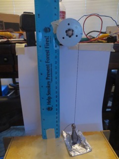
Figure 1: output of experiment
Output: The photo above is the output of the
electric motor notice the marked spot on the pulley that
is the place where to string is attached to the weight.
This was put on the side
θ=0
because if the sting was placed vertical when the
motor was activated it would violently yank the string
and ether break it or would have fluctuating data on
the data-logger. With it on the side the movement was
calm and linear.
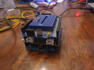
Figure 2: measurement of input
Figure 2: measurement of input
Input: Above this is one of the components
used to isolate the system on the input side. This
was set up to read voltage across the motor and was
programed to record voltage measurements every
hundredth of a second so, cent-seconds.
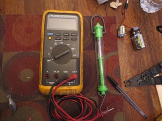
Figure 3: Calibration and current measurement.
Figure 3: Calibration and current measurement.
Other
measurements: Above is the other equipment for
measuring and calibrating the arduino and
circuit set up.
Please
review the equation and definition section
before moving to the rest of the experiment.