Electronic components, on their own, are quite fascinating. Of course, if they're not connected in a circuit, all you can do is look at them. All electronics are governed by Maxwell's equations, a set of four vector analysis equations in electromagnetism. Analyzing complex circuits using Maxwell's equations is time consuming and not very practical. Fortunately, they are not needed; developments of circuit analysis techniques, largely those from American engineer Oliver Heaviside, have reduced the required equations to simple arithmetic and algebra, provided a few assumptions are made:
1.] The rate of change in magnetic flux outside of the circuit elements is equal to 0.
2.] The rate of change in current inside of the circuit elements is equal to 0.
3.] The physical length of the circuit is much, much smaller than the wavelength of the electromagnetic waves travelling through it.
The first two rules eliminate the interference of magnetic fields within and out of the circuit. The last rule lets us assume that the electrons are travelling so fast they can be said to be affecting all points of the circuit at the same time. In very large circuits, such as cross-continent power and communications networks (and even in very small circuits such as microprocessors running at very high clock speeds) this assumption is no longer true. We also assume that the wires in the circuit have no resistance; thus there is no potential difference drop through the wires and all the action happens in the circuit components (though in reality the non-uniform potential differences on the surface of the wire are what forces current through the circuit in the first place).
In addition, there are two laws, called Kirchhoff's Circuit Laws (named after the German physicist Gustav Kirchhoff) which are essentially restatements of the fundamental principle of conservation of energy:
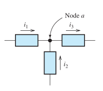
Kirchoff's Current Law: The currents entering a network node (left picture) must equal the sum of the currents leaving the node.
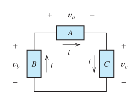
Kirchoff's Voltage Law: The sum of voltages around any closed loop (right) in a circuit must equal zero.
Circuit Simplification
The effects of multiple circuit elements can, during circuit analysis, be combined into one equivalent element for the purposes of simplification of analysis. Elements "in series" with each other in a network share one node, connected to the two elements and no other components. two components "in parallel" are connected together at each other's two terminal nodes.
Resistors in series can be summed into one equivalent resitance
Req = R1 + R2 + ... + Rn
Resistors in parallel can have their inverses (their conductances) summed into one equivalent conductance, which can then be inverted to obtain the equivalent resistance:
Req = [1/R1 + 1/R2 + ... + 1/Rn]-1
Should you be possessed to arrange inductors in series and in parellel, their combination is the same as that of resistors:
Leq = L1 + L2 + ... + Ln [Series] and Leq = [1/L1 + 1/L2 + ... + 1/Ln]-1 [Parallel]
However, capacitors in series and in parallel work the opposite way:
Ceq = C1 + C2 + ... + Cn [Parallel] and Ceq = [1/C1 + 1/C2 + ... + 1/Cn]-1 [Series]
Time Domain and Frequency Domain
When we're analyzing a circuit, we're most interested in voltage signal and current signal levels. Everything else of interest in a circuit can be calculated using those two quantities. The signals can be measured either over a period of time (time domain analysis) or over a range of signal frequencies (frequency domain analysis).
The simplest circuit to analyze is a network of resistors, which can be combined until the circuit is as simple as possible; then, using Kirchhoff's Laws and Ohm's Law, the voltages and currents are methodically found.
A circuit can also be composed of a set of resistors, inductors, and capacitors. These utilize the voltage/current equations for inductors and capacitors:
V = L[di/dt] and I = C[dV/dt]which can still be analyzed with Kirchoff's laws; the resulting analysis, however, results in a differential equation that must be solved.
The basic physics of these linear circuit elements are as follows:
RL and RC Circuit:A circuit with a resistor and either an inductor (RL) or a capacitor (RC). These circuits are largely unexciting; the capacitor and the inductor both store energy; when put in a circuit with a resistor, this energy is dissipated over time until the elements no longer store any.
LC/RLC Circuit:A circuit with a capacitor and an inductor (and perhaps a resistor). Over time, the charged capacitor discharges; an ideal inductor does not dissipate any of the energy. In addition, once the current begins to flow through the inductor, the inductor resists any attempt for the current to flow back. Thus, all the capactior charge flows through the inductor onto the opposite plate. Over a period of time, the current's rate of change becomes zero; then, the inductor does not oppose the current from flowing the other way, back to the original plate. The signal oscillates, back and forth in an LC or RLC circuit at some frequency.
One last important thing of note is the functions of capacitors and inductors in the presence of mixed signal circuits (AC and DC signals superimposed on each other in the same circuit). For AC signals, the current through a capacitor increases with time-variant voltage signals (I = C[dV/dt]) while the voltage changes, the current through a capacitor increases; at a node, then, between a resistor and a capacitor, the capacitor acts as a path of least resistance for the AC signal, leaving more of the DC signal to pass through the resistor. A capacitor used in this way is called a bypass capacitor, which reduces unwanted variant signals in a circuit (called "noise".) Similarly, the voltage across an inductor increases with time-varying current (V = L[di/dt]) in a direction to oppose the variance; thus an AC signal is resisted while a non-varying DC signal is allowed through. An inductor used in this way is called a choke.
A frequency domain analysis is both easier and a bit more difficult than time domain anaylsis. The key circuit quantity is the impedence Zof a circuit element, defined as follows:
ZR = R [Resistor]; ZL = jωL [Inductor]; ZC = 1/[jωC] [Capacitor]
Where j is the imaginary constant and ω is the circuit signal frequency. As can be seen, as the signal frequency approaches the capacitor impedence approaches infinity and the inductor impedence approaches zero. Likeways, as the signal frequency approaches infinity, the capacitor impedence approaches zero and the inductor impedence approaches infinity. This is why, in very high frequency circuits such as those seen in RF and communications, exclusively inductors are used, while in low- to mid-band frequency circuits, mainly capacitors are used.
For frequency analysis, then, basically everything becomes a resistor and a modified Ohm's law using impedence instead of resistance can be used to determine the voltage and current through the elements. Using the linear components, one can create "filters:" circuits designed to "allow" frequencies and "reject" others. For instance, a "low-pass" filter (allow low frequencies, reject high ones) can be created by putting a capacitor in series with a resistor and attaching another circuit across the capacitor terminals; at low frequencies, the capacitor impedence is very high and almost all the voltage drop is across it; thus a very strong voltage signal is outputted. As the frequency increases, however, the capacitor impedence drops; and at high frequencies, there is almost no voltage drop across the capacitor, which then outputs a very weak signal. Thus, low-frequency signals are outputted and high-frequency signals are not. As can be seen, capacitors and inductors are mostly dead weight in a DC circuit, but in an AC circuit, they become quite dynamic!