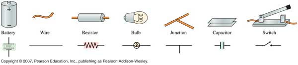
Key elements in a circuit
diagram
 http://whs.wsd.wednet.edu/Faculty/Busse/MathHomePage/busseclasses/apphysics
/studyguides/chapter23_2008/Images/23_02Figure.jpg
Understanding how a circuit works
When approaching how to solve the calculation of a circuit you will first need to draw a diagram of a circuit. To draw a diagram of a circuit you will need to know how to use the key elements shown above.
The second step to is determine whether or not the circuit is in series or parallel.
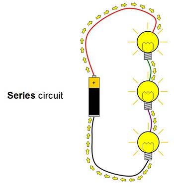
You can do this step without calculations by simply looking at how the circuit is wired. A series circuit is wired so that the wire is going through resistors from the battery and back to the battery. When drawing a diagram you will see that it's a single rectangle shape. Parallel series have 2 or more rectangular shaped diagrams in a closed circuit.
Using the image in the previous page on series circuit.
Picture to left: http://www.sciencebuddies.org/science-fair-projects/project_ideas
/Elec_p074.shtml#background
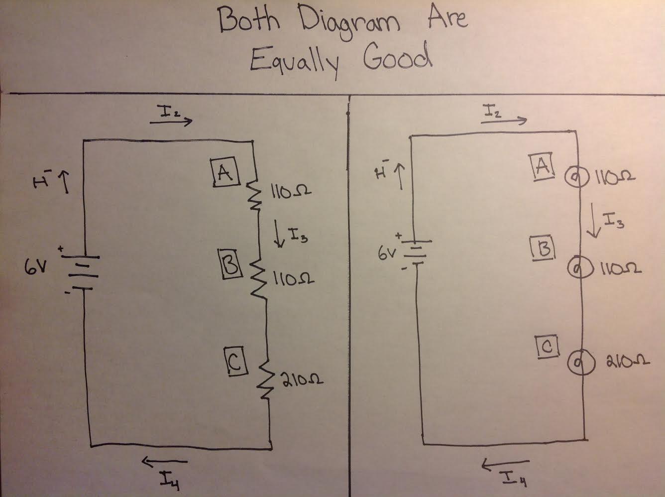
Picture to right: Provided by Kevin Chang
The picture to the left shows how the circuit would look like in a diagram format with the key elements. As you can see there are two diagrams in the right photo. This is because any device which is not just limited to light bulbs can be drawn as a resistor. Lights are in fact resistors so be definition it is okay to draw them as resistors but not the other way around.
When you figure out that the circuit is in parallel or series you can apply one of two rules, Ohm's law and/or Kirchhoff's law. For series it is always a good thumb to use just Ohm's law because the circuit is not as complex.
Ohm's Law
V = I * R
I= V/R
R= V/I
V= Voltage which is measured in (Volts)
Voltage is also known as (work done/charge) & (Joules/coulomb)
& Electric motive Force (emf) which is measured in voltage & Potential Difference which is also measured in voltage.
I= Current which is measured in (Amps)
Current is also known as (Coulombs/Second) which is the flow of electrons
(Current up to 10 milliamps (.01 amp) can cause physical pain and current up to 100 milliamps (.1amp) can be very lethal when touching a bare wire in a circuit.)
R= Resistance which is measured in ohm's (The Greek symbol for Ohm's Ω )
(All resistors have a power rating that should not be exceed. When a resistor's power rating is exceeded, it will either start to break down, smoke, or blow up.)
Ohm's law is used to calculate the voltage, current and resistance in both series and parallel circuits.
Kirchhoff's Law
Kirchhoff's Law has two parts, the Junction rule and the Loop rule.
The Junction/Node rule states that the current going into a wire is equal to the current going out of the wire. This rule is basically conservation of electrons.
Current in = Current out
The loop rule states that the sum of the voltage in a closed circuit is zero.
Voltage of the battery = The sum of all the voltages.
You have to draw the assumed direction of the current flow with an arrow.
Always assume the current is going from the positive terminal to the negative terminal to make calculations simpler.
Kirchhoff's Law is more commonly used to calculate the voltage, current and resistance in parallel circuits.
Power Equation
The Power Law equation tells us how much power a resistor is dissipating at a given current, voltage, or resistance.
P=I*V
p=(V^2)/R
p=(I^2)*R
P=Power dissipated which is measured in (Watts)
I= Current which is measures in (Amps)
R= Resistance which is measured in ohms (The Unique symbol for Ohms Ω )
Brief review on solving a circuit
Step 1: Draw a circuit diagram
Step 2: Determine if it's a series or parallel circuit
Step 3: Calculate the total resistance in the circuit
Series Circuit Resistance Total: R(total) = R1+R2+.....Rn
Parallel Circuit Resistance Total: 1/R(total)=(1/R1+1/R2+......1/Rn)^(-1)
The symbol n is the integer of the amount of resistors in the circuit.
Example: A closed circuit with 3 resistors in series have a total resistance of
R(total)=R1+R2+R3
Step 4:Apply either Ohm's Law or Kirchhoff's Law accordingly.
Step 5: Apply the Power equation after finding all the currents in all resistors and the voltage across each.
Calculating The Electric Diagram Above In The Second picture On The Left Diagram With The Given Data
Known Values: Unknown Values:
Battery = 6Volts Current 1 (coming out the battery)=?
Light Blub A =110 Ω Current 2 (right before first light blub)=?
Light Blub c =110 Ω Current 3 (between light A and B)=?
Light Blub b =210 Ω Current 4 (between light c and battery)=?
Use ohms Law:
Voltage= Current * Resistance , (V=I*R)
Applying the resistor total to get the amount of total resistance we use
R(total)=R1+R2+R3
Once you get the resistance total you apply Ohm's law to find Current 1 by doing
I = V / (R(total))
Current 1= .014 amps
Current 1= Current 2= Current 3= Current 4
Because of the uniqueness in series and years of testing the current in a series circuit is always constant around and the only thing that changes is the voltage within the resistor.
The same could be said about parallel circuits, however, Voltage is always constant and the only thing that changes between resistors are the current. (Current always travels in the path of least resistance)