Construction of apparatus
Background
The construction is based on MIT's experiment: Weather in a tank. The parts were obtained based on a similar construction. The drive mechanism uses a friction wheel that spins a turntable. Wooden mounts were shaped in the Physics department's machine shop at UAF. The pictures on this page were taken incrementally as the project matures.
Tank constraint
The first fixed parameter of the design and construction process is the DC motor. This was already purchased, which means that the motor's specifications impose a constraint on the size of the tank. The dimensionality of the motor also yields additional concerns.
The weight of the water is estimated by considering the dimensions of the tank to be 16" x 16" x 16";

Although this value provided an upper limit, the actual tank dimensions are approximately 15" x 15" x 15". The agreed maximum water level is about 8" from the bottom. The tank dimensions also fit within the available torque provided by the motor.
Drive Mechanism
The drive mechanism is the main component of the apparatus. The tank is driven by a friction wheel. The DC motor drives a drive roller with neoprene (35A Durometer) surface to transfer the torque to a rotating dial. The value of Durometer selected provides a hardness between a rubber band and a pencil eraser. Although the drive roller is only 4" in diameter, the offset axel of the motor allow for some clearance for the rotating dial.

DC motor on wooden supports.
|

Friction wheel rotates the platform.
|
The bottom mount is affixed to a wooden board with wood glue. The platform dial is mounted on a lubricated turntable designed for "lazy-susans." The rated weight is about 500lbs, which should be sufficient for the weight of the tank.

Rotating platform mounted on the turntable.
|

Platform's surface.
|
The rotating platform is mounted directly above the motor casing. Since the DC motor is rather large, this method provides a more compact feel to the appratus. One disadvantage of this is that the height clearance between the rotating platform and the motor's body housing is short. This restricts expandability in this region such as the addition of electrical slip rings.

Front view of the rotating platform and motor.
|

Rear view of the rotating platform and motor.
|
There are switches on the DC Speed control that needs to be configured in order to provide proper voltage and current parameters. The wooden mounts are then attached with hinges and latches. This provides accessibility to the motor.
Preliminary structural test of the mount and the turntable was performed by placing a body on the rotating platform.
Tank
The tank is assembled from 15" x 15" x 0.10" plexiglass pieces. Acrylic epoxy is used to bind the plexiglass pieces into a box. After the epoxy is cured, the tank is then lined with silicone sealant to prevent against leaks.

Assembled tank using five pieces of
plexiglass sheets.
|
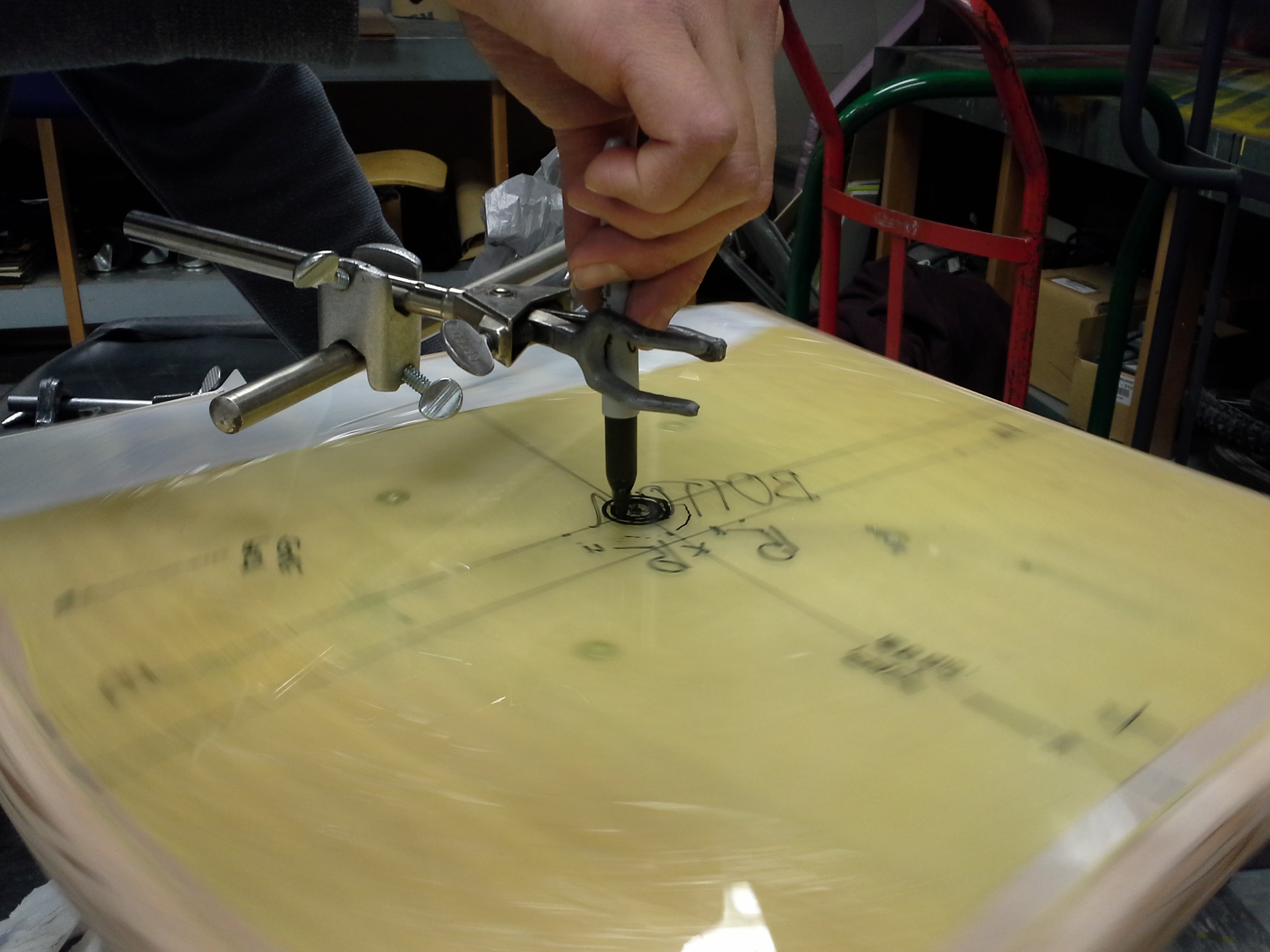
A method to determine the center of rotation
of the tank.
|
Small brackets are mounted on the rotating platform to hold the tank during rotation. This method allows the tank to be portable.
Completed apparatus
The completed apparatus sits on a cart that allows easy transport. A simple halogen work light illuminates the tank. Laboratory mounts support a camera in the rotating frame. The tank has a minor wobble that is visible during video capture.

An experiment being performed in the
tank.
|

A circular plastic sheet allows for a
cylindrical boundary condition.
|
The entire construction phase took approximately three weeks to complete. Further improvements will rectify the current definciencies in this project. The working title for the project during the construction phase was the Cubic Hydrodynamic Experimental Apparatus Project.