The efficiency of this bridge is defined as the load it can support divided by the mass of the bridge itself. The goal is to optimize this relationship to maximize Ebridge.

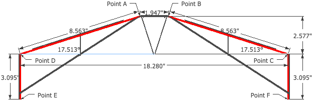
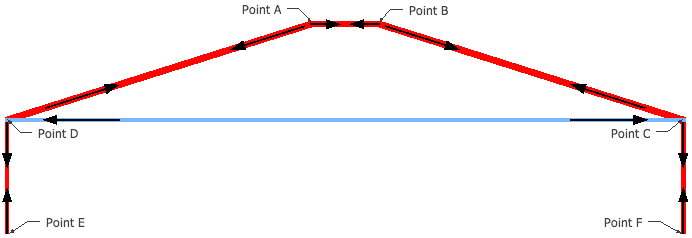
Because the geometry of the truss will not be changed, both the mass and the maximum load will ultimately be a function the cross sectional area of each of the members. Our load-bearing members here will be AB, AD, BC, DC, DE, CF. There is bracing refered to as zero-force members, whose weight will not change. Because there is symmetry down the center of the bridge, we will just consider one side and will multiply appropriately. A summation of the masses of each member, plus the zero-force members is as follows:
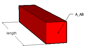

Each member, for example AB, has a cross sectional area AAB, length, and density of 0.0159 lb/in3.
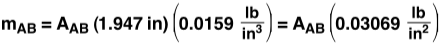
This equation is similar to each of the individual members, resulting in a the following bridge mass:

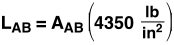
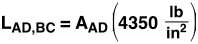
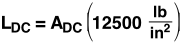
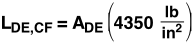
The total load, Lbridge, is limited by the weakest point on the bridge, whether it be a member failing (under either tension or compression) or a joint failing. Members AB, AD, BC, DE and CF are all under compression. 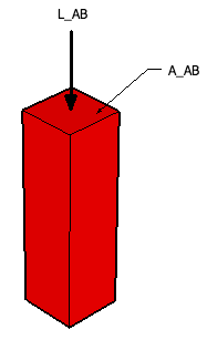 Only member DC is under tension. For the material we are using (pine), the maximum compression and tension before failure are 4,350 lb/in2 and 12,500 lb/in2, respectively. This means that for a member under compression, the largest force that can be placed on it is equal to the cross sectional area (in2) multiplied by 4,350 lb/in2; the same holds true with tension at 12,500 lb/in2. For our members, we have

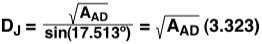
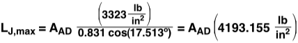
There is one more variable to consider for the calculations. The joints at D and C are the weakest in the entire design. The sheer strength of pine is equal to 1000 lb/in2. Due to the design of these joints, the width of the contact area between member AD,BC and member DC will be equal to the width of member AD,BC, which is the square root of AAD. The distance (length) of the joint contact area will be equal to
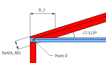
Since the members have square cross sections, the width of AD is equal to the height, which is measured in the image to the right. The total contact area will now be equal to the length times the width of member AD.

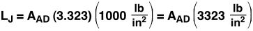
This concludes that the maximum load LJ the joint will take with contact area AJ, before failing is,
There is now a way to calculate the largest load, Lmember, that each part of the bridge will sustain. However, to find what the largest load that the entire bridge will support, Lbridge, we need to know how much of the overall load will be distributed over each member and on the joints at D and C.
When a load is added to the bridge, a force will be placed upon all of the members. Determined by the geometry of the bridge, and arrived at through static analysis, each member will experience a force equal to the following percentages of the full load.


Setting the maximum load before failure of each member equal to the percentage of Lbridge that is exerted on the member (FAB = L AB) and then solving for L, we get the maximum load of the bridge as a function of the area. The equation for each member below assumes it is the weakest member in the design. Doing this allows us to consider how much the bridge will support if said member fails first.
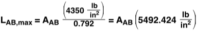
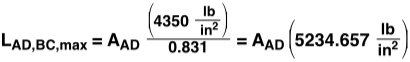
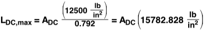
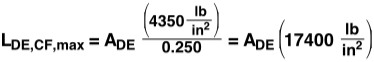
Because there is no way to create an equation for the strength of the bridge as a function of the size of its members (because the smallest value from the above equations dictates the strength of the bridge), it is best to create a spreadsheet of all the possible designs using the four sizes of pine that are on hand.
