Three types of channel connections for MHD generator are possible. They are Segmented Faraday, linear Hall-type and disk type. Now let us see one by one as follows
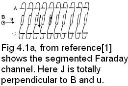
a.) Segmented Faraday channel
In the Faraday channel, the load current and the electric field are jy and Ey components form generalized Ohm's law.
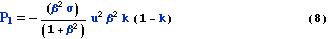
The electrode segmentation for insulation of the axial Hall field is necessary. Because, continuous electrode walls, the Hall current flows downstream in the plasma and returns through electrode walls. As a result, there is a inclination in the current flow direction which increases with Hall parameter β=μeB. There is decrease in power density by 1/(1+β2). But this Faraday power density is for uniform plasma case. So the Faraday channel is kind of a constant voltage generator. Generally for seeded (connected) combustion plasma, the conductivity mainly depend on the temperature, i.e. the conductivity non-uniformity in thermal boundary layers, no mater how long the segment is the electrode potential drop occurs and so current is not uniform from anode to cathode. Though the Faraday generator model has the advantage of high power density, on the other hand the large number of DC power terminals with different voltages and currents must be converted into AC for transmission. The number of electrodes can be reduced to two-terminal DC output by linear Hall geometry and disk-type channel.
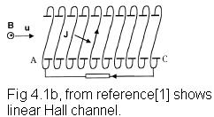
b). Linear Hall channel
In Hall channel the primary Faraday current in the uxB direction is shorted out by connecting opposite electrodes with wire, with metallic frame or by internally shorting through plasma. The load current and electric field are jx and Ex with local power density of Hall channel is given by equation bellow with load factor K ≡Ex/(-uBβ).
When β ≡ μeB»1 the Hall power density becomes like Faraday case. That is with high electron mobility therefore low collision frequency between electrons and ions. This shows the Hall effect that the current is primarily due to the JxB force on the electrons. For this reason, “the hall generator is adequate to the inert gas-driven, closed-cycle MHD generator with non-equilibrium plasma with elevated electron temperature in the range of 5000-8000 K under temperature of an order of 1000k” words directly from reference[1]. In this case argon or helium can be used. Since argon has minimum electron temperature and helium because of its high mach number flow (that is high motional induction field can be obtained).
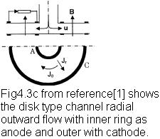
c). Disk type
The load current and electric field are jr and Er with loads are connected between anode and cathode. The local power density and loading factor is same as the above case except in radial coordinates that is ur and Er. In the disc generator plasma fluids flow between the center of a disc and a duct wrapped around the edge. Here pair of circular Helmoholtz coil is used above and bellow the disk. The Faraday current flow in a perfect dead short around the periphery of the disc while the Hall current flows between the ring of electrodes near the center and the ring electrode near periphery. Thus giving more efficient and closer magnetic field to the flowing fluids(it has simple parallel field liens).

| Figure shows three type of channels |
|
A. Segmented Faraday channel
C.
Disk type
|