Figure
3: Power Supply Removal
Once
the screws have been removed
the transformer should sit on a hinge and it can be rotated
upward. As a
safety precaution the load contacts on the transformer should be
short
circuited with an insulated screw driver. This is a last
resort effort to make sure the circuit providing power to the
transformer
is turned off. If for some reason it was still turned on there would be
some
arcing occurring across the screwdriver and the output terminals of the
transformer. Please make sure the circuit is turned off so that this
does not
happen.
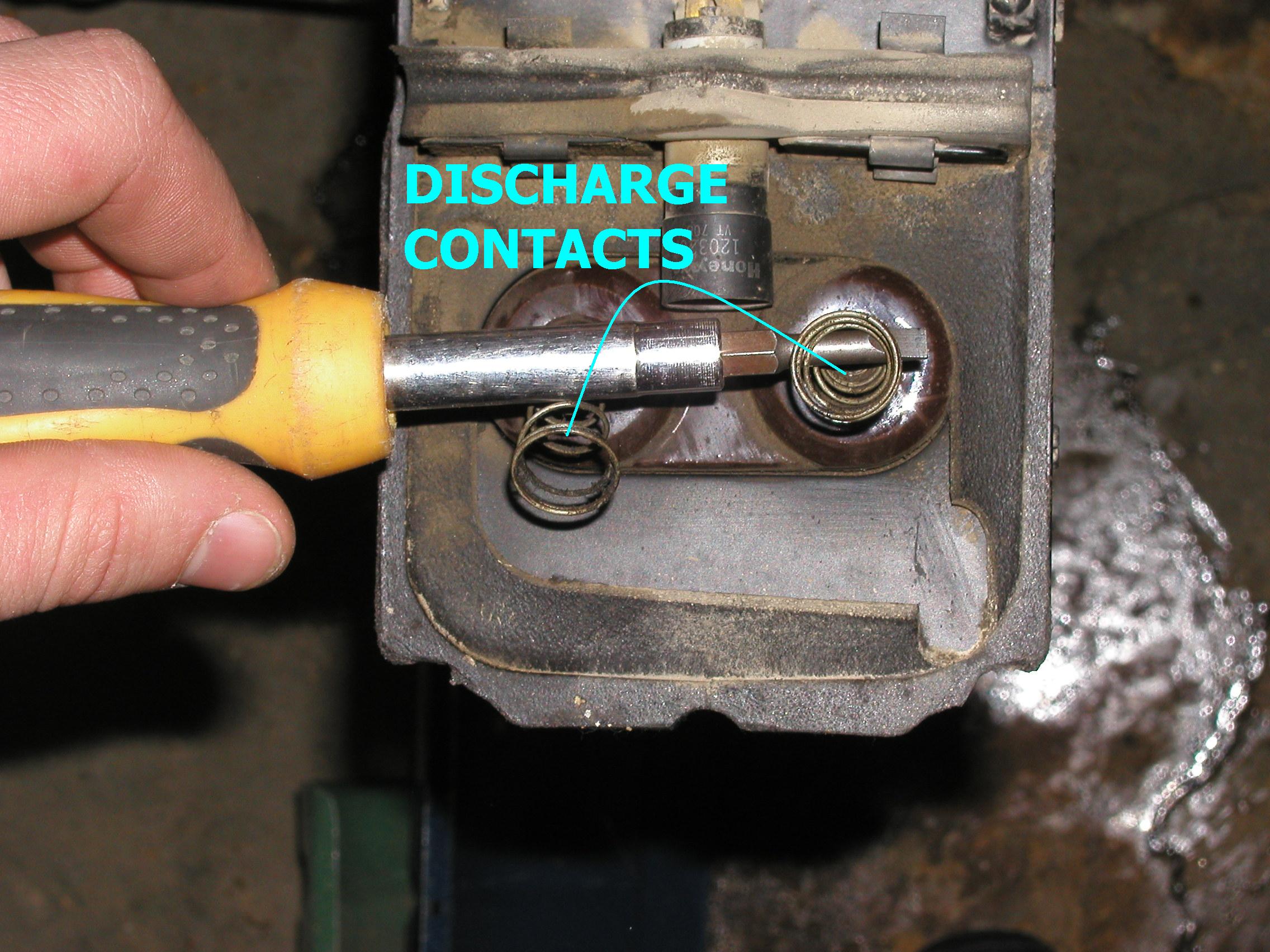
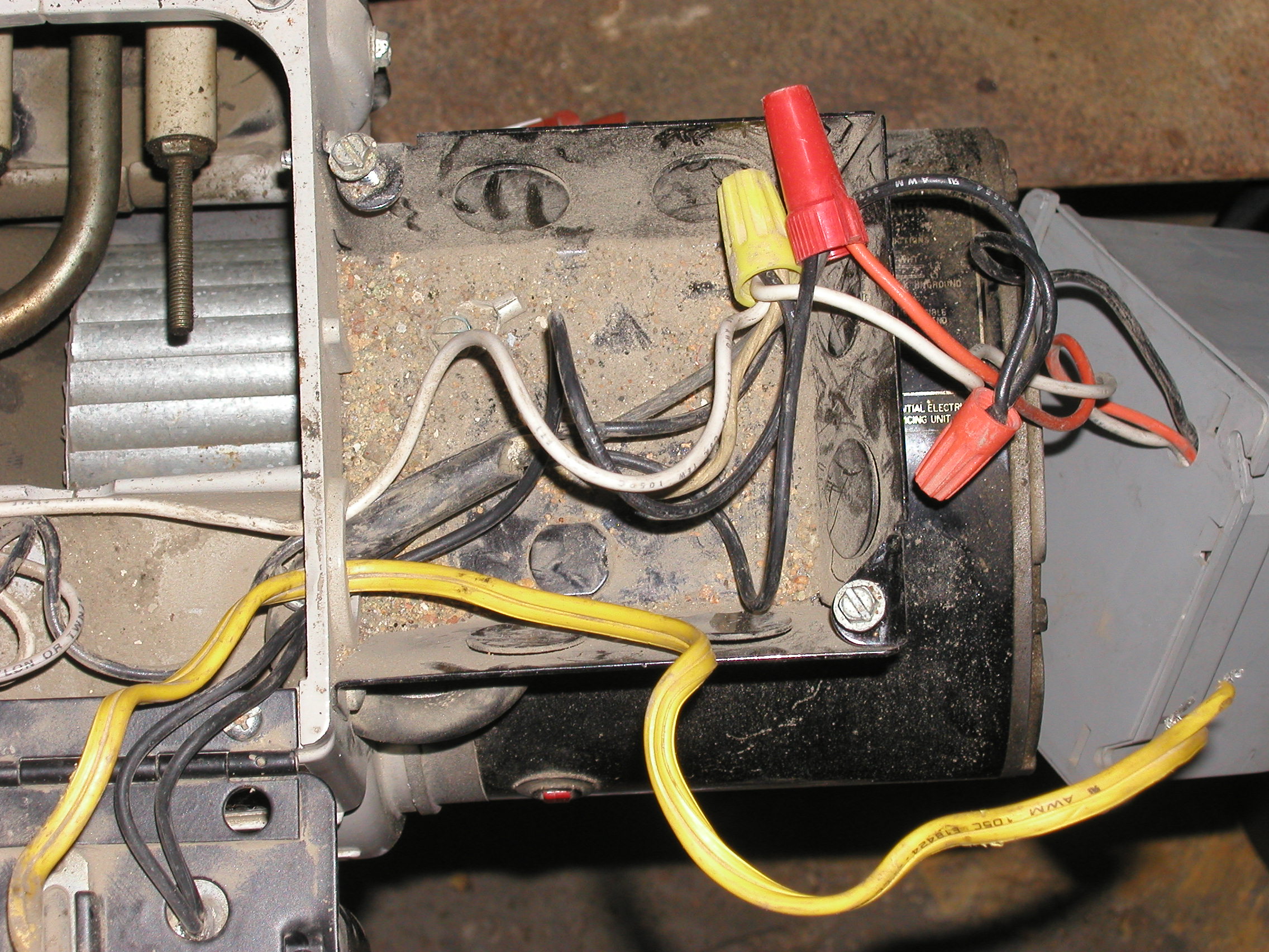
Figure
4: Discharging contacts
There are a few wire nuts that
maintain an electrical connection to the supply side of the transformer
that
will have to be removed. Just twist off the wire nuts and pull the
connections
apart. A word of advice, draw a diagram for the connections if you have
never
done this before. Other wise when you go back to reconnect it you will
most
likely have forgotten what hooked up to where.
Figure 5:
Wire Connections
Finally there should just be a
couple of bolts to remove and the transformer can be taken off the
boiler. Then
you are off to the building stage of the Jacobs Ladder.