The
aerodynamics of fluid trajectories can
vary enormous amounts with minute
changes of shape from the projectile.
Many instinctive hunches are proven to
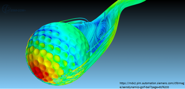
be incorrect. For instance, do you know
why golf balls fly further when they
have dimples on them? The dimples create
a pocket of turbulence which protect the
ball’s surface and minimizes drag.
Nerf Dart Aerodynamics
In
order to understand the physics of the
foam dart’s trajectory, the darts
themselves need to be understood as
well. Proper dart trajectory is a clean
straight path with a slight curve
towards the ground due to gravity. If a
dart fishtails, descends too quickly, or
is inaccurate, the dart design is at
fault. Many flaws can be avoided with a
proper understanding of what is going on
during the dart’s flight. A few factors
which need to be taken into account when
analyzing anything in flight, are the
center of mass and center of pressure.
The center of pressure is the point at
which the sum of all the pressure
vectors act on the dart and the center
of mass also can be called the center of
gravity is the point where the weight of
the dart is acted on by gravity. The
center of mass follows the trajectory
curve. Both the center of mass and the
center of pressure are approximately in
the positions as shown in the figure.
The dart, as soon as it exits the barrel,
starts descending due to gravity acting on
the mass. The dart is not pointed directly
in the angle of the trajectory and instead
is at an angle against it shown in the
diagram as the angle of attack. The result
is that the air flow pushes the center of
pressure from an angle below. Because the
point of pressure is behind the center of
mass, the air flow will pivot the dart at
the center of mass making the tip point
upwards. If not properly stabilized, these
forces could oppose one another and cause
the dart to tumble through the air
instead.
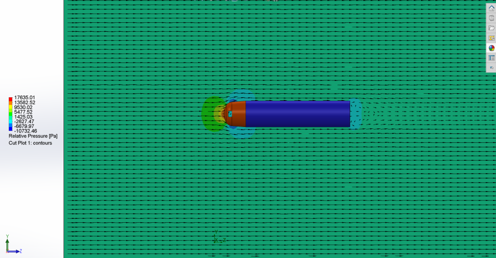
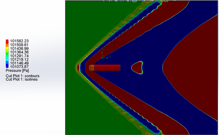
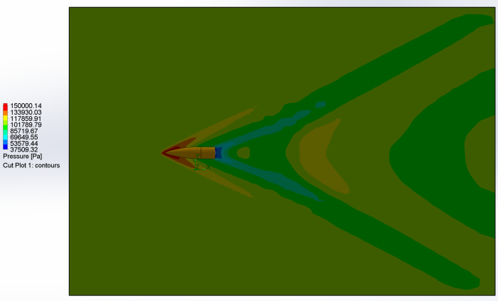
With the information calculated earlier,
we can put the CAD model into Solidworks
and get simulations of the air pressure,
velocity, acoustic power level, and
thermal levels while traveling 153.88
m/s in 101,325 Pa at 293.2 K.
This model shows
the relative pressure of the air surrounding the
dart in pascals
This model shows
the velocity of the air around the dart in m/s and
Mach
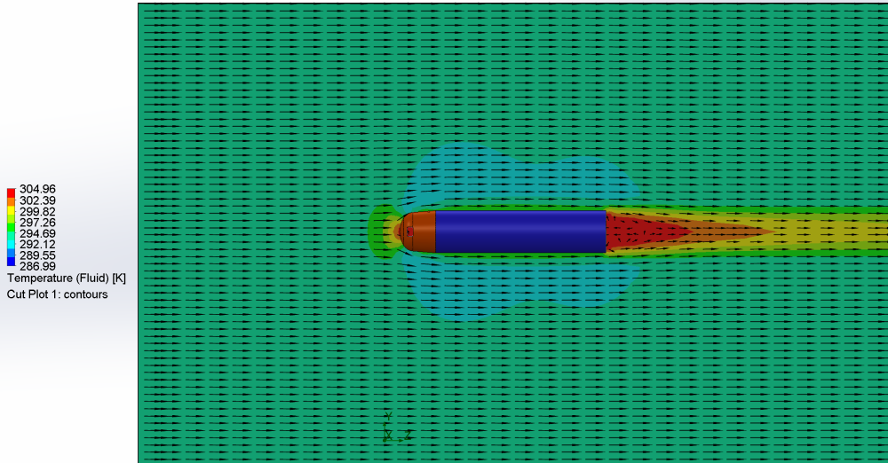
This is
the temperature of the air in Kelvin
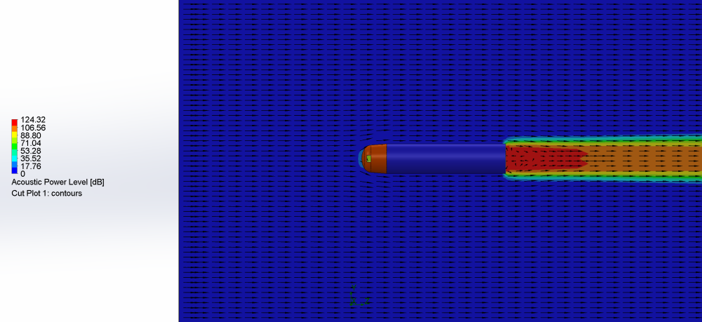
This is
the acoustic power level measured in Decibels
Drag Coefficient
Opening up the goals in the Solidworks flow
simulator, we can plug in the coefficient of
drag equation to get the approximate value
for drag. The average result shown below was
0.6212 which is a very reasonable value.
Looking at the drag coefficient of a normal
cylinder, at right, we can see for the
length of the standard Nerf dart has a drag
coefficient of 0.67. Our 0.6212 value makes
sense since there is very little difference
from the Nerf dart to a cylinder, besides a
slightly pointed tip. We will use the drag
coefficient value later when calculating the
trajectory.
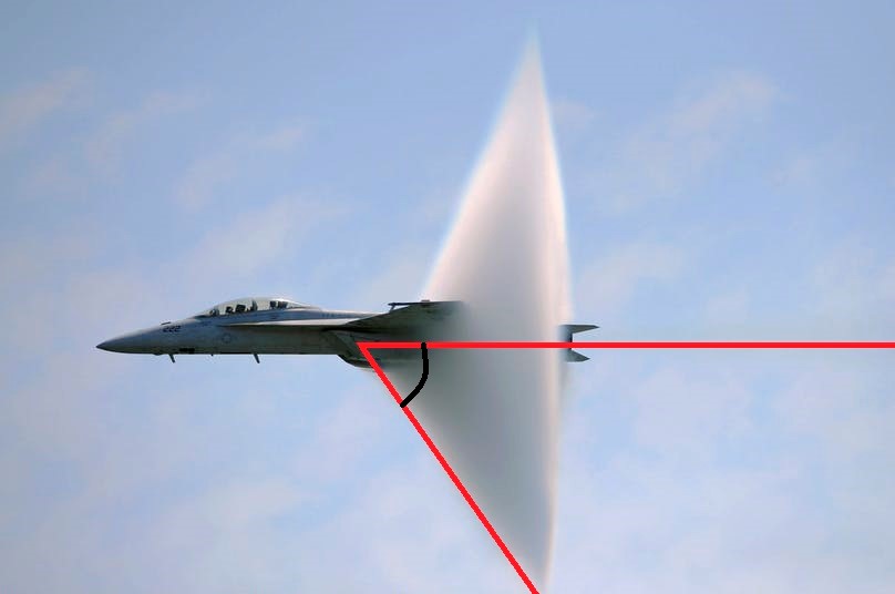
In
an atmosphere, supersonic (speeds
greater than the speed of sound)
projectiles compress the air in front of
the object forming a cone shockwave
which gets thinner as the speed
increases until they merge together,
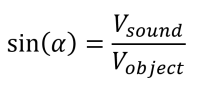
shown at right. An equation that
summarizes the angle of the cone uses
half the angle to make an upside-down,
right triangle with an object on the
ground.
Behind
the object is negative pressure and the
higher-pressure air in front normalizes
when the object passes. This is known as
an “overpressure profile” or an N-wave
and can be described by Weibull’s
formula:
Where:
2410 is a constant based on 100kPa, m is
net explosives mass, and V is volume of
given area.
Due to the need for volume, Weibull’s
formula works best in a controlled
environment with a measurable space.
Now, taking our Nerf dart again, we can
see the shockwaves produced when
traveling Mach 2.0 at STP.
Here
are the airflow models of Nerf dart at
high speed vs normal speed pictures
rendered in Solidworks. It is apparent
that the design of the Nerf dart was not
intended for supersonic flight due to
the severe low pressure area behind the
dart.
https://en.wikipedia.org/wiki/Sonic_boom
https://arunachalobserver.org/2018/10/24/thunder-blasting-air-likely-sonic-boom/
Angle alpha (α) shown as half the angle of
the cone