Source: http://hyperphysics.phy-astr.gsu.edu/hbase/magnetic/indcur.html
Main Ideas and
the Potential of Wireless Energy Transmission
Electrical
power transmission is very important to distribute power to
our homes and buildings. It is not uncommon for there to be
power transmission lines running through cities in developed
countries. Physical wires are not the only outlet for power
transmission however. Wireless energy transmission typically
makes use of some kind of electromagnetic delivery of energy.
One particular way to accomplish this is to exploit Faraday’s
Law (the law states that for any magnetic field there is an
induced electric current perpendicular to the field lines) to
convert the energy from a magnetic field into electrical
power. Other methods include microwave transmission or laser
transmission. There a few ways to go about designing this
feature in power transmission. Examples include transformers
in power grids and battery chargers in electric toothbrushes.
The purpose of transformers is often to convert some input
voltage into a reduced output voltage. In order to understand
how transformers work, the relationship between current in a
conductive wire and its induced magnetic field must be
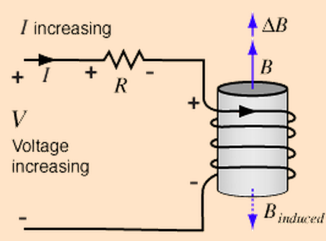
understood. Observe the figure below, representing a DC
circuit with some of its wires wrapped around an iron core:
Source:
http://hyperphysics.phy-astr.gsu.edu/hbase/magnetic/indcur.html
Faraday's Law
states that the counter electromotive force (this resists the
current flow from the supply by Lenz's Law) is equal to the
number of turns in the coil times the rate of change of
magnetic flux through the iron core. This expression is shown
below:

Source:
http://hyperphysics.phy-astr.gsu.edu/hbase/magnetic/indcur.html
Analyzing the circuit in the figure, we can calculate the
electromotive force (emf) using Kirchhoff's Voltage Law. If the
number of turns of the wire is known, the time derivative of the
magnetic flux can be calculated. With this information in mind,
observe the
arrangement of a typical transformer in the diagram below:

Source:
http://en.wikipedia.org/wiki/Transformer#/media/File:Transformer3d_col3.svg
The basic operation can be described as follows: The current
through the first set of windings induces a magnetic flux
through the iron core or transformer core. The magnetic flux
flows through the transformer core in a loop, passing through
the second set of windings. The magnetic flux in the transformer
core induces a current in the second set of windings, actuating
a voltage across this set of coils. As the diagram suggests, the
magnetic flux flowing through the first set of conductive coils
also flows through the second set of conductive coils. If we
know the voltage across Vp and the number of turns for both
conductive coils, the voltage across Vs can be calculated. The
voltage Vp is supplied by an external DC circuit wrapped around
this iron core. The relationship that governs the voltage across
Vs is derived below:

Source: Microsoft Word
Equation Editor
To reduce the input voltage as described, Ns (number of turns
in input coil) must be less than Np (number of turns in output
coil). This is the basis of the operation of a transformer in
many electrical circuits that require some reduction of voltage
for a device. In the case of the electric toothbrush charger,
the operation is very similar to the operation of the
transformer in principle.
Observe
the diagram shown below:

Source:
http://www.planet-science.com/categories/under-11s/our-world/2011/07/how-do-electric-toothbrushes-charge-through-plastic.aspx
Step by step, energy into the electric toothbrush can be traced all the way back to the plug socket. First, a conductive wire is wrapped around an iron core in the charger. When current is supplied to the wires in a coil, a magnetic field that flows through the axis of the coiled wire is induced. The iron core concentrates the magnetic flux through itself. The iron core is then hooked to the other end of the charger. In the electric toothbrush, there is an open cavity that has another set of conductive wires wrapped around the cavity. When the electric toothbrush is placed onto the charger, the iron core is placed between the conductive coil. It should be noted that to charge a battery, you simply need to supply current in the opposite polarity of the battery. To accomplish this in the electric toothbrush the magnetic field in the iron core induces the current in the opposite polarity (through Faraday's Law) in the electric toothbrush. In a nutshell, this is how power is transmitted without any need for physical contact between conductive wires. As can be seen, this type of transmission is very short ranged, and the main incentive for this type of design was to reduce corrosion of metal parts. In recent years, scientists have conducted research into longer range energy transmission. Research has been focused on a method called resonant wireless power, which will be elaborated more later.
--------------------------------------------------------------------------------------------
Previous - Home
- Next