The Physics Behind
Dove-Tailed Joints, and Force Equations.
- History
The dove-tailed joint has been
around for thousands of years. According to
Appalachian joinery, "Some of the earliest known
examples of the dovetail joint are in furniture
entombed with mummies dating from the First
Dynasty of ancient Egypt, as well as the tombs
of Chinese emperors". In the last couple hundred
years, the dovetail design has become most
popular with Appalachian Indians. The
Appalachian even created their own style, called
the Appalachian style, which is the most common
style in use today. The Appalachian style makes
use of spaces between the logs for moss or other
types of chinking to be used for insulation. The
older dovetail building were built very sturdily
by skilled craftsmen, and have stood the test of
time, and quite a few of them still stand today.
-
Physics
The dove-tailed joint uses some simple laws of
physics in order to snugly join the logs
together, in such a way as to keep them from
wanting to separate. The
intricate design of the dove-tail could best
be compared to a combination of two wedges
stacked on top of each other, with the top
wedge rotated ninety degrees to the first
wedge.The dove-tail is
a double-compound joint that is cut so that
every log is placed on a downhill slope of the
other log with the downhill slope towards the
center of the building. They also have a
vertical flat spot at the start of the
dovetail which allows the stacked log to rest
against, so that the logs have a backstop to
prevent slipping towards the center of the
cabin. The dovetail uses the physics of
gravity to snugly pull the walls together from
the weight of the walls, roof, and snow load,
since the weight is acting to bring the logs
down the slope. With the logs sloped towards
the center of the building, with a backstop,
they are not inclined to pull apart.
Photo courtesy of the author
- The above photo's are taken by
the author from the house he built using
dovetail construction. The first picture
is a close up of the dovetail corner of one wall
which shows the double-compound angle that is
utilized to keep the corners together. The
picture also shows the gaps between the logs.
The gaps will be utilized to run electrical
wires in, then they will be filled with
insulation, and the logs will be permachinked to
fill the gaps. The second photo shows a dovetail
jig that is being utilized to cut a dovetail
joint with a chainsaw. The jig gives the perfect
angle for the dovetail, and saves countless
hours of laying out and cutting the joints by
hand. The sawmill that is shown is the workhorse
that is necessary to cut all of the beams for
the cabin. The third picture shows the authors
dovetail log cabin under construction with the
roof partially done.
Force equations
When designing the various members of
a dovetail log cabin, it is important to be able
to analyze the various forces acting on certain
members, such as the roof line and eaves, so as
to be able to tell how strong to engineer them.
There are a couple of basic force equations that
come from Newtons
Second Law, which states that for every
action there is an equal and opposite reaction.
The common way that engineers find forces in
house members which are in static equilibrium,
is by drawing a free-body diagram
which replaces members with forces and then
gives directions to those forces relative to an
axis system. Similarly, a kinetic diagram
is used to show forces on objects that are
moving. The next step to analyzing the forces on
a member of the house (assuming static
equilibrium), is to use the three standard force
equations. Those three equations state
that the sum of forces in the x-direction equals
zero, the sum of forces in the y-direction
equals zero, and the sum of moments equals zero
(Statics & Dynamics P.113). Very
often however, the forces are not all lined up
on a given axis, so vector decomposition
is necessary to break the vectors into their
respective X&Y directions.
The following picture shows a good example of
some members on the roof that are replaced by a
free-body diagram.
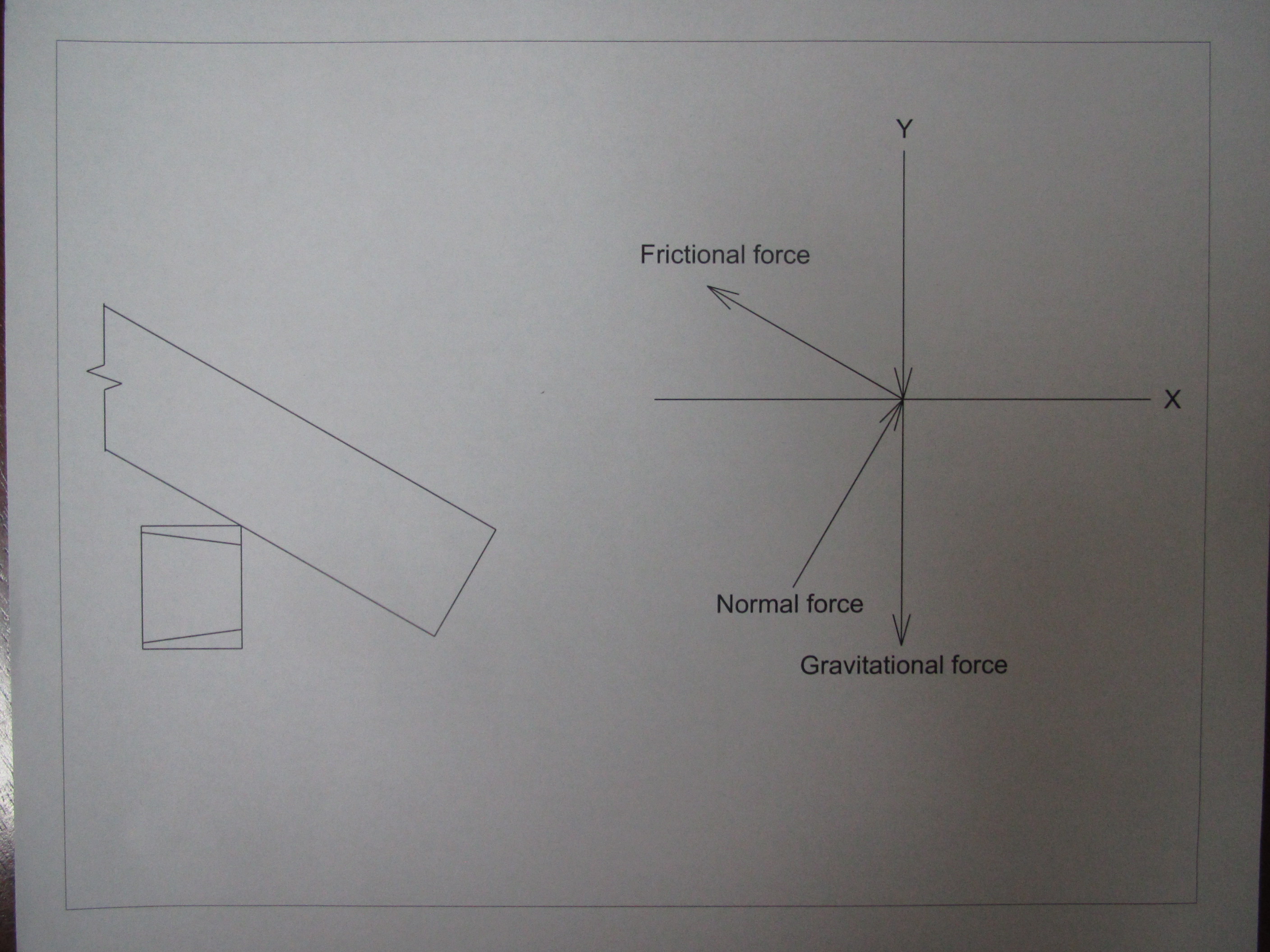
Free-body diagram forces in the top log. Drawing
was produced by the author using an auto-desk
educational product.
|


