| Robert
Stirling was the Scottish inventor of the first
practical example of a closed cycle air
engine in 1816, and it was suggested by Fleeming Jenkin as
early as 1884 that all such engines should therefore generically be
called Stirling engines.[Wikipedia] These engines are not very common and are often known by the novel name, 'hot air' engines. This is not entirely correct since there are relative hot and cold sides, but its lends an idea to how they work. Until recently these engines were not used as a means of work in the practical sense, but are gaining popularity. "In the spring of 1983, Professor Ivo Kolin of the Universiteb in Croatia pleasantly startled the Stirling engine world by publicly exhibiting an engine running on the heat of boiling hot water." [James R. Senft] In 1983, an engine that could run on a 100 degree (Celsius, 212 F) temperature differential was a big deal, which brought competition to the study of Low-Temperature Differential Stirling engines. By 1990 James Senft produced an engine that would run on a one half degree (Celsius) temperature differential. "This means that Stirling engines can now utilize low grade heat sources for their operation ranging from passive solar or geothermal energy to industrial process waste heat." [James R. Senft] |
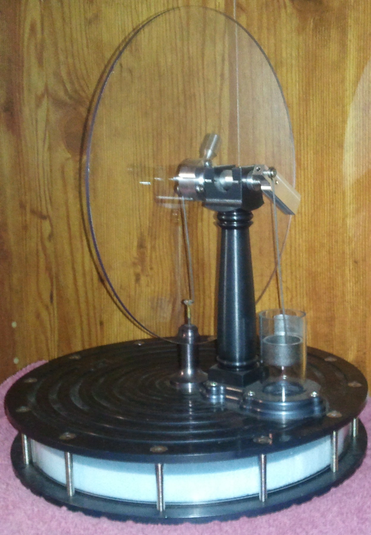 |
This is an example of a Low-Temperature Differential (L.T.D.) Stirling engine produced by M.E. students at UAF. This one will run on a ten degree temperature differential and is in the process of being tuned for better performance of future engines. Most people have only seen engines like this in an academic setting since it produces very little power and are relatively expensive to manufacture. Notice the geometry of the air chamber in this engine. The plates have a large surface area compared to the volume and the short stroke of displacer and power piston. These are characteristics of engines considered to be L.T.D. engines. Construction: Machined aluminum, rigid 9/16 foam displacer, graphite/Pyrex Airpot piston cylinder, graphite lined displacer gland, ball bearing rotating assembly, Lexan/poly-carbonate displacer chamber and flywheel. |
 |
Notice
the geometry of this engine. The stroke vs. bore are
close to equal for the displacer and power piston. This engine required a much higher temperature difference than the engine above. Notice this one is heated by the lamp oil and wick torch underneath part number "5." Also these engines tend to run at much higher rpm's due to the geometry of the displacer. |