Basic Design Process for a Yagi-Uda Antenna
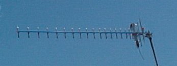
http://www.electronics-tutorials.com/antennas/antenna-basics.htmIn order to see how the information summarized in the technical portion of this site relates to antenna design, a simple design will be outlined. The antenna chosen for this is the Yagi-Uda antenna, a highly directional antenna with a significantly high gain factor.The first step in modeling an antenna is to determine what frequency range it will cover. Our target frequency is going to be 2.4GHz (a common commercial wireless frequency). Using the wavelength - frequency equation it is discovered that the wavelength of a 2.4GHz signal is roughly 12.5 cm. This tells us that if the antenna were a single dipole, it would have to be at least half this length to receive the signal, because otherwise the antenna is not able to tell what kind of signal it is picking up. This is due to the fact that the antenna would have no zero reference point from which to continue propagating. Since a Yagi-Uda antenna is being constructed instead, it can be seen that it differs in that an array of dipoles is used. With only one element active (usually the second to last), the remaining elements, refereed to as directors, guide and focus the signal toward the active element.

http://www.ee.surrey.ac.uk/Personal/D.Jefferies/yagiuda.htmlAs a basic rule, the directors should be roughly 1/4 a wavelength apart. This makes sure that when a signal is picked up in the outermost element, and is induced in each element down the line toward the driven element, the signal remains in phase. In fact this mutual inductance of the multiple directors has an adding affect on the signal, boosting its strength, which is responsible for the antennas characteristically high gain factor (to an extent, the number of directors dictate how high the gain factor is). Now that the signal has been passed down the line of directors, it induces current in the driven element and the reflector, which should be positioned approximately 1/2 a wavelength behind the active element. The reflector picks up "spare radiation," from both the directors and the driven element, further focusing it. Presto! You have an antenna! Although this is a VERY simple design it would still work, not as well as an engineered antenna, but it would still work.
Additional variables come into play in real life, such as environmental and operating conditions, but those are beyond the scope of this page so were not discussed.
Links