Power Supply Units

Sources:
Corsair:http://www.corsair.com/~/media/corsair/product%20photos/psu/ax-series/ax1500i/large/ax1500i_psu_sideview.png
openPSU:
http://www.corsair.com/~/media/corsair/product%20photos/psu/ax-series/ax1200i/large/detail_axi_psu_cutout_a_open.png
AC to DC
A power supply is made up of a series of capacitors, transformers, resistors, switches, heat-sinks, and much, much more. As discussed in previous pages, certain components of a computer, namely the graphics card, require large amounts of power to operate at their full potential. Because hardware components vary in power draw, selecting a power supply with a sufficient wattage rating is crucial in having an operating computer.The main purpose of a power supply is to convert alternating current into an appropriate direct current so the computer can power its components. However, the power supply is also tasked with outputting apropriate voltage ratings to ensure each component of the computer receives the correct potential. A fan for example may require 12 volts while a processor may need only 3.3 or 5 volts. Unfortunately, most wall outlets worldwide supply voltages of 110 or 220 volts. How does the power supply change this high potential into a feasible voltage for the computer components? The answer is by using a transformer.
Transformers
Transformers are used in electric circuits to either "step up"
or "step down" the voltage running across it. In terms of power
supplies, it is apparent that in order for the power supply to
convert the 110 or 220 volts from the wall to a lower voltage,
it must have a step down transformer. Step down transformers are composed of two winding's called the primary winding and secondary winding. The primary winding is the side of the transformer that receives the high voltage and low current from the energy source. The secondary winding outputs lower voltage but higher current to the load (computer components). In order for this voltage step down to occur, the primary winding must have more turns in its wire coil than the secondary winding. This scenario is portrayed by the diagram below:
Step Down Transformer
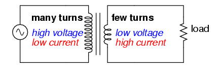
When an alternating current is ran
through a coil of wire, it generates a magnetic field with
magnetic flux present in the middle section between the two
coils. This magnetic flux indicates that the magnetic field
is either increasing or decreasing and therefore an induced
magnetic field is created to counterbalance this change in
the magnetic field. From this induced magnetic field, an
induced current is generated in the second coil of wire and
depending on whether or not the second coil has more or less
coils than the primary, the resulting voltage and induced
current are stepped up or down.
An equation can be derived from the fact that
if two winding's have an equal number of turns in each coil,
their voltages are the same.
Hence,
where V1
is
the voltage in the primary winding
V2 is the voltage in the secondary winding
N1 is the number of turns in the primary winding and
N2 is the number of turns in the secondary winding.
This equation can be rearranged for V2 such that
V2 = V1 * (N2/N1)
Therefore,
because the voltage in the secondary winding is directly
proportional to the number of turns, having less turns
results in a lower voltage for the secondary winding.
step down transformer source:
https://sub.allaboutcircuits.com/images/02134.png