Exploring the anatomy of a simple jet engine
All jet engines have five basic components: Fan, Compressor, Combustor, Turbine and Nozzle

Fan: The fan is the first part of the jet engine from the front. Air is sucked into the engine and sped up by the fan. The fan also splits the air into two parts (except in the case of turbojet engines), air that will go through the engine's core and air that bypasses the other components of the engine to be pushed out of the back. Air that travels through the core will be acted upon by the compressor, combustor, pass through the turbine to provide energy to power the engine and finally leave through the nozzle. Bypass air is sped up and pushed out the back of the engine to create most of the thrust for the aircraft.
Compressor: The compressor is the first component in the core. It is composed of multiple fans each with many blades, the compressors become progressively smaller, squeezing the air under adiabatic conditions and creating an increase in the pressure of the air that passes through them which increases the potential energy of the air. There are two types of compressors, axial and centrifugal. Air flows through centrifugal compressors perpendicular to the axis of rotation and air flows through axial compressors parallel to the axis of rotation. Most jet engines today use axial compressors because they can be strung together relatively easy to create a greater compression force while still being smaller in diameter than centrifugal compressors. The process has no heat exchange so it is adiabatic and it is also reversible. Since it meets these requirements the process is called isentropic and therefor the isentropic flow equations can be applied to find work done by the compressor per mass of airflow.
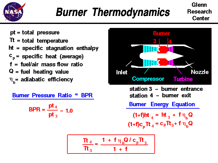
Combustor: The combustor or sometimes called the combustion chamber is a doughnut shaped chamber where compressed air is mixed with jet fuel and ignited by an electric spark causing the gases to expand to create a high temperature, and therefore high energy airflow. Since heat is added by the combustion reaction, the process is not adiabatic therefore the temperature and pressure cannot be simply related. Therefore the Burner Energy Equation must be used to determine the Thermodynamics of the combustor allowing engineers to set the final temperature (Tt4) by simply changing the fuel/air mass flow ratio. This value determines the Engine Pressure ratio and Engine Temperature which both in turn determine the engines thrust.

Turbine: The turbine is composed of rotating and non-rotating blades called rotors and stators respectively. The turbine's rotors are spun by the high energy airflow that leaves the combustion chamber. The spin of the rotors causes the compressor and the fan to spin. Work done by the air that leaves the combustion chamber is transferred from the turbine to the compressor and fan through the central shaft. The stators keep airflow from spiraling around the axis of the turbine by bringing the flow back to parallel to the axis. Energy is lost in the form of temperature and pressure. The work done by the turbine can be found by using the well known conservation of energy equation and the isentropic flow equations. This allows engineers to determine the work done by the turbine by fixing the pressure and temperature of the airflow that leaves the combustor.
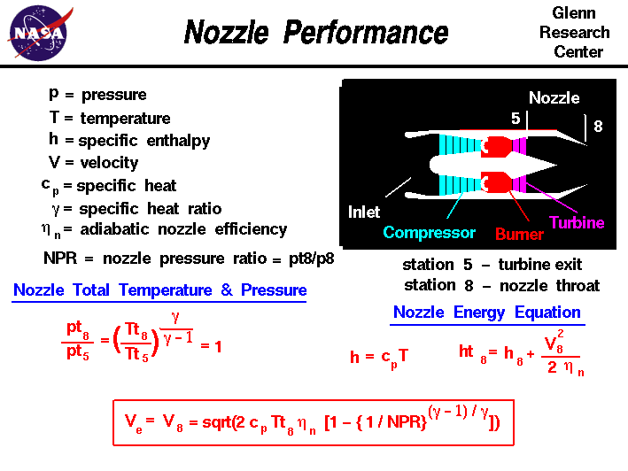
Nozzle: The Nozzle is the final part of the engine and is where the exhaust airflow is shot out of the engine to create thrust to propel the engine. Some nozzles mix the hot airflow that leaves the core with the cold airflow that comes from the fan, which creates a more efficient and quieter fan. The pressure and temperature throughout the nozzle are constant and nozzle performance is described by the equation below which gives the velocity that airflow leaves the nozzle which is used in the thrust equation to find how much thrust is produced by the engine.


