Basic Turbine Theory

History              
Justification
Air flow           
Engine temperature ratio
High bypass fan

A Brief History

· The basic theory of turbine engine can be traced back to 150 B.C. in Alexandria, Egypt. A man named Hero is said to have invented a steam powered "Whirligig" toy that had no real purpose but to look cool.

·Around 1500 Leonardo Da Vinci sketched a device that could be placed inside of a chimney stack and would circulate a spit for roasting meat.

· In 1629 Giovanni Branca designed a jet principal that can be traced to the operation of primitive machinery.

·A drawing of an invention called Newton's Carriage was later found and while Newton helped in the design, it is said to be originally designed by Willem Jako Gravesande.

·The first actual patent design of a gas turbine engine is dated 1791 by John Barber, which had all of the same essential working parts as today's modern turbine engine.

·In the early 1900's design production was in full swing in America. 
Sanford A. Moss, a pioneer in the development of a turbosupercharger that was used in WWI, was at first unsuccessful due to his design needing more power in than it could produce. It was enough however for Ross to start General Electric Company's gas-turbine project.  Credit behind the idea of GE's turbosupercharger belongs to French patents by Rateau.

·Frank Whittle is credited to have the first flying test aircraft in 1941which turned out to be successful with a “Gloster E28/39.” (Kroes, Wild,1995).


Newton's Steam wagonFrank
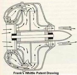
          Image 3&4  courtesy of: http://www.thaitechnics.com/engine/engine_intro.html

Aeolipile
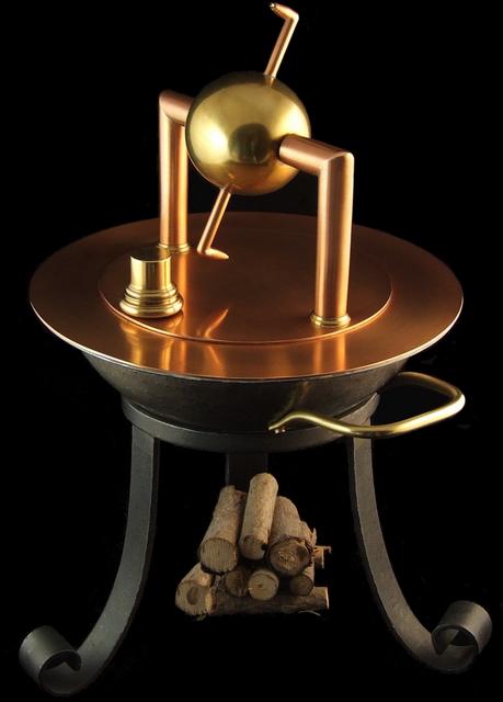
Image 2 courtesy of: http://modelengines.info/aeolipile/
-Justifications-
(While there are a number of different turbine engines, I will focus mainly on the Turbofan type engines)
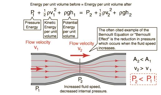
  A working understanding in physics theory is important for this topic.
  • Turbine engines are for the most part a long tube that transfers the movement of air into mechanical motion. By compressing air through the inlet of the turbine, adding fuel and letting the expansion of the fuel turn a "fan" that is linked to the intake fan,  it produces thrust while supporting the continued cycle.
  • In some modern environments the cycles are described as SUCK, SQUEEZE, BANG, BLOW.
  • Some of the most important material properties of turbine engines are weight, density, temperature, pressure, and mass. I will discuss these properties and how they apply to the physics of turbine engines on airplanes. 
Turbo
Image 5 Courtesy of : http://cs.stanford.edu/people/eroberts/courses/ww2/projects/jet-airplanes/how.html

Basic laws of physics that apply to turbines


·The thrust of a turbine engine can be explained by Isaac Newton's laws of motion; more particularly the second and third law.

·Newton’s second law, acceleration of a body is directly related to the force and indirectly proportional to mass of the object. This concept can be understood through the means of a very basic and powerful equation used today in all forms of physics

·Force = Mass x Acceleration.

·Meaning that in order for a reaction to take place or a displacement of an object, there must be a force, not just any force though, one with enough acceleration to overcome the mass of the object.

·Acceleration can be explained as the change in velocity (or speed); the interval at which an object increases it's velocity.

· Newton’s third law, for every action there is an equal but opposite reaction, describes the turbines action of taking a continuous airflow, compressing it, adding fuel and converting mechanical and thermal energy into thrust.

components-turbine-engine.gif
Image 6 courtesy of: http://www.free-online-private-pilot-ground-school.com/turbine-engines.html
Air Flow
...and Bernoulli's Theorem

  • Bernoulli, a 17th century scientist/mathematician, discovered the principal that defines the action of air through a turbine engine and more.
  • Bernoulli developed a theory based on a few principals:
  1. The fluid is incompressible and not viscous.
  2. There is no energy loss from the air and the wall of the pipe/orifice.
  3. There is no heat energy transferred across the boundaries of the pipe to the fluid as either a heat gain or loss.
  4. There are no pumps in the section of pipe under consideration. (Saurabh Sharma, 2014)
  • "Bernoulli discovered that air acts as an incompressible fluid would act when flowing at subsonic flow rates. The principal is stated as follows: When a fluid or gas is supplied at a constant flow rate through a duct, the sum of pressure (potential) energy and the velocity (kinetic) energy is constant."(Otis, Vosbury2002)  
  • When air flows through an orifice the pressure decreases, velocity increases, and the temperature decreases.
  • What is this all saying? Air is a bit different than a fluid although it acts as though it were a fluid through an orifice, meaning that by compressing it tightly, one could compress tiny molecules of air into a very confined area, mix in fuel in its vapor form, and ignite the fuel air mixture.
  • Igniting the fuel/air forces the mixture to covert it's stored potential energy into thermal and mechanical energy, turning the rear turbine blades.


Bernoulli
              principal equation
Image 7 courtesy of: http://hyperphysics.phy-astr.gsu.edu/hbase/pber.html
Engine
              tenperature ratio
Image courtesy of: https://www.grc.nasa.gov/www/k-12/airplane/etr.html
Engine Temperature Ratio

  • Turbine engines are generally designed in different stages, the significance is usually the temperature difference ranging from the "hot section" to the "cold section".
  • The cold section is described as the inlet, or front section intake where the air enters the turbine and is pushed through the larger inlet into a smaller orifice where as described by Bernoulli, when a fluid is pushed from a larger tube to a restriction the pressure and temperature will decrease, and the velocity will increase.
  • From the cold section the air flow's to the compressor section where the fuel is added.
  • The compressed fuel/air mixture travels to the burner can where a spark is ignited and the mixture expands with great velocity.
  • As the hot gases are escaping the outlet they are being directed by layers of fans pointing a specific direction in order to give more momentum to the turbine blades that are directly connected to the front cold section blades completing the cycle.
High Bypass Turbines

In the recent years a new type of more efficient turbine engine has been introduced that actually boasts its ability to run a 5:1 ratio of fan to engine thrust, where in one case of the Pratt and Whitney 4000 only 20% of the thrust comes from the engine core, the other 80% comes from the large ninety four inch fan on the front.
1. Inlet.
2. Bypass fan.
3. Turbine inlet (beginning of cold section.).
4. Compressor.
5. Burner can.
6. Turbine blade stage that coverts the hot expanding air to spin the compressor blade.
7. Turbine blade that converts the hot expanding air to spin the inlet blades.
8. Exhaust section.
9. Bypass section where most of the thrust is being produced.
High bypass wiki
Trubo fan flow
Image 9 courtesy of: http://www.grc.nasa.gov/WWW/k-12/airplane/Animation/turbtyp/etff.html
Title Page
Bibliography