Charged
Coupled Devices (CCD's)
An
extremely mainstream digital imaging technology is the
Charged Coupled Device (CCD). They are the imaging sensors
that appear in nearly every type of digital camera on
the market today. Essentially, a CCD consists of an array
of small cells or pixels. Inside these cells are tiny
photosensitive devices. These small devices are designed
such that they will behave like "buckets" that
will collect charge and hold it until it is drained out
of the system (i.e. it is directly analogous to a capacitor).
These cells are created out of a semiconducting material
that will give off free electrons when a photon of light
strikes its surface. The more photons that hit the cell
(i.e. the brighter the light for a given amount of time),
the more electrons there are in the bucket, however, these
cells are only sensitive to the light's intensity,
not its color (Thomson 1).
This
brings up the very important point made in the "Attributes
of Light" section - how to obtain a color image in
the visible spectrum if you can't have a single cell that
can automatically record the color of the light that's
hitting it. The solution, as mentioned previously, is
to utilize the colors red, green, and blue to create all
the colors that the human eye can discern. This can be
accomplished by grouping repeating patterns of two alternating
cells. Each one of these cells has a one of three different
color filters on it; either red, green, or blue. A diagram
of a typical CCD pixel can be seen in figure one and a
typical RGB CCD layout can be seen in figure two.
Figure
One (Cross-sectional view of a typical CCD cell (or pixel))
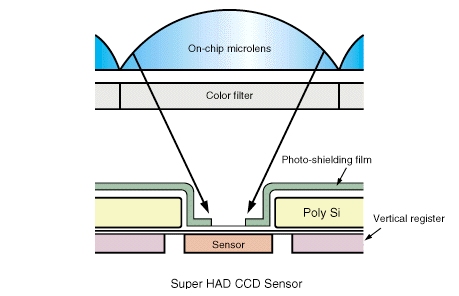
(image
courtesy of Sony
Semiconductors)
From
figure one, it can be seen that the small lens behaves
very much like the glass lens discussed in the focal plane
section, and indeed it does, however, it is essentially
meshing a still infinite group of focal points onto a
sensor that will merge them all into one. Ultimately,
this is how and where most of the information is lost,
as the microlens and sensor can not be made infinitely
small. Hence, the sensor has to be made as small as is
possible to produce an image with as much data in it as
is possible. To sum up this point, the more CCD sensors
that are on a single CCD array at the focal plane and
the smaller the CCD pixels are, the higher the resolution
of the resulting image and the more information the recorded
image will contain. A good example of this is an earth
orbiting weather satellite. If it took an image of the
earth with a 6 RGB pixel CCD, the resulting image would
look like six big blocks. However, if it's taken with
a 5 million RGB pixel CCD, a beautiful picture of the
earth will result.
Below
in figure two can be seen a typical RGB CCD layout.
Figure
Two (Diagram of a typical RGB pixel layout)
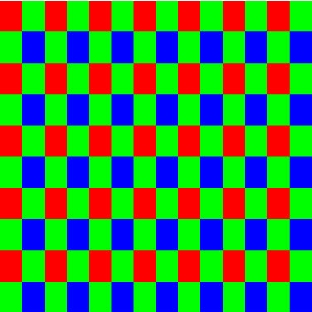
(image
courtesy of duncantech.com)
As
can be seen from figure two, the cells are situated in
columns of alternating colors such that red, green, red,
green is in one and blue, green, blue, green is in the
one next to it before the column patters are repeated.
This may be confusing at first, as there is 25% more green
than there is red or blue in the system, however, this
excess of green is advantageous, as our own eyes are much
more sensitive to the color green than they are to blue
and red (Spectral Configuration Guide, 4). Furthermore,
the colors can be manipulated as much as is desired to
make the colors appear correct, as once the CCD array
is read by the hardware in the camera, software in the
camera runs it through a set of algorithms in order to
merge the intensity data from the CCD's pixels into color
information that is then saved into a typical digital
format, such as JPG or TIFF. Typically, one pixel in a
JPG or TIFF file is comprised of four cells (one red,
one blue, and two green) from a CCD array.
A
simplified example of how these colors are combined through
their intensities and how the cells might charge up for
one pixel in a JPG or TIFF file is as follows:
First, let's say each cell can have an intensity value
of 0 - 255 (8 bits). Also, one pixel, as previously stated,
has one red, one blue, and two green cells. Now, let's
take a 1 second exposure of a blue river. At the beginning
of the exposure, each cell and sensor within it will start
out with zero charge in its bucket. As time increases,
however, they will begin to charge up to a maximum value
(maximum intensity = 255 - if all cells have an intensity
of 255, the color output is white, if all zero, the color
output is black), however, they will charge up at different
rates due to the filters (in this case, blue will charge
faster than green or red). The charge versus time graphs
for each color would look something like figure three
below.
Figure
Three (Charge versus time graphs for an RGB pixel inside
a CCD cell for the scenario listed above)
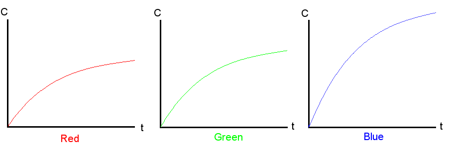
So
after one second, there is more blue than red or green.
For instance, after one second, the red sensor detected
an intensity of 50, the green of 80, and the blue of 150.
Once the intensities of the charges are read off from
the sensor, the intensity is then registered inside the
software of the camera. These intensities are then merged
together to form a single pixel. From this example, the
pixel would have this color:

For
film, however, the process is a bit different, but it
still follows along similar lines. To see the basics of
how film creates an image, click here.

